The Future is Here: Integrating X-band Radar for Next-Level Detection and Imaging
February 8, 2024
Basics of X-band Radar
As you can imagine, radar, originally developed by the military in the 1930s, has undergone significant changes. New technologies enable the delivery of transmitters and receivers with greater precision, more efficient power use, and significant size reduction. And in recent years, electronic control elements for beamforming have become increasingly popular, providing more flexibility and increased benefits in the latest generations of X-band solutions.
X-band radar occupies 8-12 GHz and has superior target resolution and improved support for operations that require higher accuracy. It operates with a smaller antenna size than lower frequency counterparts—enabling more compact antenna arrays—as well as offering greater sensitivity for detecting smaller objects because of the small wavelength used.
The advancements in X-band have given way to significant growth in the global radar industry. According to Allied Market Research, the industry was worth $32.56 billion in 2019 and is expected to grow at a CAGR of 4.7% from 2021 to 2028, reaching $44.35 billion, driven by increased demand in the automotive and defense industries, territorial battles, and advancements in technology.
Of course, with new advancements, there are also new design challenges. This blog post provides excerpts from a recent Qorvo Design Summit webinar on integration guidance for X-band applications.
Take a Deeper Dive
.png)
Explore this topic in greater detail as part of the Design Summit series with Qorvo experts. These webinar sessions cover advances that are enabling revolutionary next-generation technologies
Key Webinar Takeaways
In the Qorvo Design Summit webinar, X-band Radar Application with Integration Guidance, Fouad Boueri, Qorvo Senior Product Line Manager, covers the following key points:
- The fundamental building blocks for steering electronic phased arrays are the transmit/receive (T/R) modules (shown in Figure 1).
- Circuits within these modules carry out basic tasks, including amplifying the transmit signals, filtering noise from the received signals, and using beamforming to shape and steer the elements in the radar system by varying the amplitude and phase of each element. As systems become increasingly configurable, solutions that offer expanded functionality—with several applications residing in one device—are becoming common.
- Components included in the RF front end are the PAs and LNAs that provide signal amplification, phase shifters, attenuators, switches and filters that provide signal conditioning, and mixers and oscillators for signal translation (i.e., frequency up and down conversion).
- An important trend in the industry is the increased integration of digital control over high-frequency functions. Other innovations include using a broadband front-end to support multi-function systems and controlling the elements precisely to improve digital beamforming.
- Limiter – protects the LNA from damage by large incidents of power at the input.
- Switch – routes the RF signal between the transmit and receive paths with optimal signal-to-noise ratio (SNR), power level, and isolation between T/R and provides robustness on the input from the antenna.
- Phase shifter – controls the relative phase for each antenna element of the array system in order to electrically shape and steer the beam.
- Digital step attenuator – attenuates the RF signal by controlling power and gain for beam steering and tapering.
- Filter – provides signal conditioning such as isolation, coexistence and mitigation of interference.
- LNA – provides amplification of the received signal and provides system sensitivity.
- Power amplifier – amplifies the transmit signal with high efficiency.

Figure 1. X-band radar T/R modules
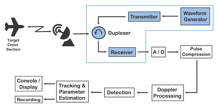
The block diagram of a typical, modern X-band radar (Figure 2) shows the organization of key components. As with any system design, there are tradeoffs that are required to establish the most optimal performance. Below the block diagram is a list of transmit and receive attributes engineers must navigate through to attain optimal system performance.
.png)
Figure 2. Next-Gen X-Band Radar
The webinar provides details on each functional component area – defining the main function of the component in the system as well as what tradeoffs need to be considered during the design. Below is a short summary of this review, but for more detail, refer to the webinar.
Component and function:
Over the past couple of years, the above-listed individual discrete components have migrated toward integration – helping with system size reductions, performance and ease of design. Additionally, when integrating these individual functions, several designs also provide a fully matched module, making system design easier and less costly. As an example, let’s compare the IMFET versus Pre-Matched Transistor (Figure 3)
The tradeoffs when comparing an Internally Matched Field Effect Transistor (IMFET) with a pre-matched transistor package are shown in Figure 3. Note that for the IMFET, there is no matching network; all matchings happen within the transistor. The pre-matched transistor must be matched on the PCB before reaching the 50-ohm connector, as shown on the right side of the table.

Figure 3. IMFET vs. Pre-Matched Transistor
Building Innovative Solutions for X-band Applications
As shown in this video, many factors affect decision-making during the design of an X-band solution, requiring careful evaluation of the strengths and weaknesses of the various options. We hope this webinar will provide a level of solid information to aid in your decision-making and demystify the X-band issues you may encounter during project design. Download the full webinar to find out more.