Solving Brushless DC Controller Design Challenges
January 27, 2020
Solving Brushless DC Controller Design Challenges
This post first appeared on the Mouser Electronics website, by Robert Huntley, a frequent contributor to Mouser Electronics’ blog.
Brushless Motors Gain Traction
Brushless DC (BLDC) motors have become the default choice of motor for a wide range of battery and line-powered equipment and appliances. More reliable and requiring significantly less maintenance than their brushed DC motor counterparts, brushless DC motors have also benefited from a broader industry understanding of how to control them using simple microcontroller algorithms. In today’s complex and sophisticated control applications, brushed motors also create too much electrical noise, which means designers need to employ substantial electromagnetic immunity mitigation techniques. Audible noise from brushed motors is also now considered undesirable, particularly for portable battery-powered appliances such as vacuum cleaners and personal power tools, including jigsaws and drills/drivers.
Manufacturers construct brushless DC motors using fixed permanent magnets on the rotor drive shaft and a series of field windings (typically three) on the inside of the motor casing. Switching the current through the three field windings in sequence results in rotation of the drive shaft. Controlling the pulse width and the switching frequency of the drive to each field coil provides control of motor speed, acceleration, and output torque. A closed-loop feedback of the rotor’s operation to the three-phase motor control algorithm is required to closely monitor and control the current state of the drive shaft’s rotation. The two most popular methods of providing this feedback are:
- Affixing an encoder disk or other form of rotational sensor to the rotor shaft.
- Sensing the back electromagnetic field induced by the rotor’s permanent magnets within the field windings. Field-oriented control (FOC) refers to using the induced field voltage.
A sensorless method helps improve overall motor reliability as well as reducing the bill of materials (BOM) cost.
The Architecture of a BLDC Motor Controller
As discussed in the section above, there are three distinct circuit functions required for a brushless motor controller. These three distinct circuit functions are achieved through:
- A microcontroller that runs the motor control algorithm
- Pulse Width Modulation (PWM) circuitry that provides the switching signals
- A power output stage that drives the motor
An analog-to-digital function converts the shaft rotational sensor signals into the digital domain for processing by the microcontroller. When designing an embedded motor controller, there are several design considerations. The initial factors that help shape the overall design of an embedded motor controller are:
- The power/torque required
- The power supply source
- The shaft speed
Today’s fast-paced prototype-to-production focus tends to dissuade design engineers from developing a custom controller using discrete parts. Thus, the more popular design route is to use an off-the-shelf microcontroller to run the control algorithm. Most microcontrollers incorporate a wide range of ADC/DAC conversion functions in addition to different peripheral interface options, clocks, and timers. A suitably equipped microcontroller might provide the majority of the required circuit functions, but many microcontrollers tend not to be optimized for motor control applications or incorporate the necessary half/full “H” bridge motor drive functions. Also, energy management is a necessary function of most applications today and is especially important in motor control applications where the energy efficiency rating is usually a key selection criterion for customers. Power management ICs are available, but this requires the engineering team to integrate another IC into the design, increasing the BOM cost and board space requirements.
 As more consumer and industrial motor-based appliances adopted a brushless DC motor design, the need for a device that includes all of the necessary functions drove Qorvo to develop a full-featured power application controller (PACTM). Qorvo’s PAC5556 Power Application Controller® (PACTM) integrates all the required analog, power management, and gate drive signal sources within a single, compact package.
Introducing the Qorvo PAC5556
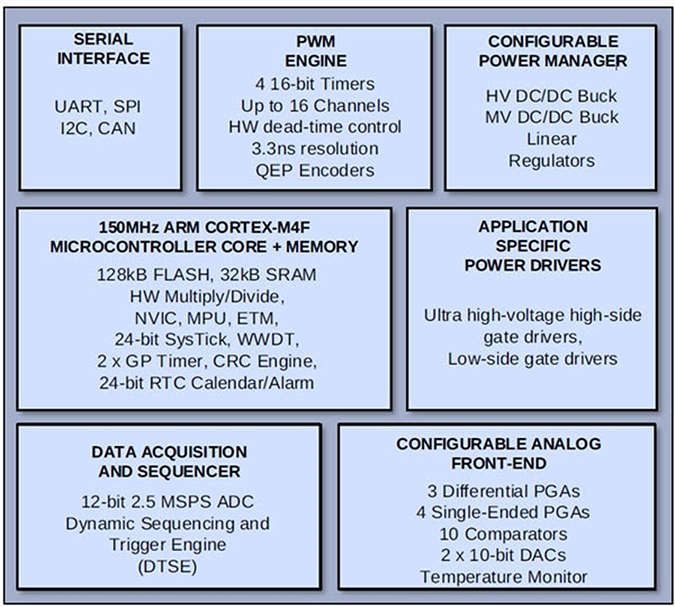
The Qorvo PAC5556 Power Application Controller® (PACTM) is supplied in a slim QFN-52 package, can operate motors up to 600VDC, and incorporates a comprehensive set of features and functions necessary for any BLDC or smart energy application (Figure 1). The highly integrated PAC architecture makes the Qorvo PAC5556 especially well-suited for applications where the PCB is shrinking, such as white goods, compressors, and power tools.
 Figure 1: The image provides a simplified functional block diagram of the Qorvo PAC5556 power application controller. (Source: Qorvo)
A 150MHz 32-bit Arm® Cortex®-M4F microcontroller core with 128kB of user-programmable FLASH memory is at the heart of the device. A nested vectored interrupt controller (NVIC), capable of accommodating up to 25 external interrupts, provides a wake-up function to enable the device to come back from different sleep modes. Clock-gating of the 24-bit real-time clock permits low-power operation. The microcontroller unit (MCU) also incorporates a high-speed 12-bit ADC. Configured for little endian operation, PAC5556’s Arm® Cortex®-M4F microcontroller core includes hardware support for multiplication and division, DSP instructions, and an IEEE754 single-precision Floating Point Unit (FPU). The integrated FPU supports complex high-resolution control algorithms, such as the ones used with FOC. The high-performance features of this MCU enable design engineers to easily implement complex real-time algorithms, safety software, and diagnostics in their applications.
A pulse-width modulation (PWM) engine provides the drive signals for the motor gate drivers. Capable of fine motor control, down to 10ns, the PWM engine consists of four 16-bit timers and 14 channels.
The analog front end of the PAC5556 is highly configurable and offers both differential and single-ended programmable gain amplifiers, ten comparators, 10-bit DACs, programmable over-current protection, integrated VM ADC sampling, and I/Os for inter-connectible and programmable signal sampling, feedback amplification, and sensor monitoring of multiple analog input signals. These analog capabilities make the device suitable for use in field-oriented control or sensor-based BLDC control applications.
Other salient attributes of the Qorvo PAC5556 include a configurable power manager and application-specific power drivers. The configurable power manager contains a multi-mode switching supply converter that permits the IC and the motor drive circuits to be powered using a buck converter topology. On-chip linear regulators provide the IC supply rails, and the power management functions control the available sleep and hibernate modes. Designers can optimize the power manager for run-time and standby modes. PAC’s very small standby current results in very good battery life in battery-powered tools when not in use. In equipment that is always connected to an AC (like white goods), the power manager can help with ENERGY STAR ratings. The power driver block provides all the necessary high- and low-side gate drivers suitable for use in a variety of different motor drive configurations, including half-bridge and full “H” bridge.
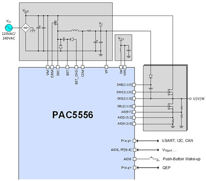
A simplified diagram of the Qorvo PAC5556 used to drive a BLDC motor is illustrated in Figure 2.
 Figure 2: The image provides a simplified diagram of a Qorvo PAC5556 used to control a BLDC motor. (Source: Qorvo)
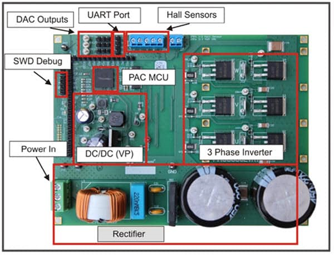
To aid the prototyping and development process, an evaluation board based around the Qorvo PAC5556 is available. The Qorvo PAC5556EVK1 is a complete fully-featured evaluation and prototyping platform for the PAC5556 (Figure 3). The evaluation board supports gate driving for up to three half H-bridge inverters with ratings up to 220VAC or 450VDC. A virtual COM port connection to a computer together with a GUI-based software suite permits configuration and control of any application running on the PAC5556EVK1.
 Figure 3: The Qorvo PAC5556EVK1 evaluation board. (Source: Qorvo)
Conclusion
Brushless DC motors have become a popular choice for use in a wide range of consumer and industrial appliances. As brushless motors are incorporated into a broader range of applications, the ability to quickly design, prototype, and test motor controllers is key to speeding the overall product design process. As a result, design engineers need a device that integrates all the required analog, power management, and gate drive signal sources within a single package. The highly integrated Qorvo PAC5556 Power Application Controller meets the need for a compact power control solution that reduces energy consumption, bulk, and noise in consumer and industrial motor applications. This design also meets tighter board space requirements and keeps the BOM cost to a minimum.
Have another topic that you would like Qorvo experts to cover? Email your suggestions to the Qorvo Blog team and it could be featured in an upcoming post. Please include your contact information in the body of the email.
