How Carrier Networks Will Enable 5G
October 17, 2017
 Active Antenna Systems, beamforming, beam steering,
Fixed
Wireless Access (FWA): the transition to
5G is bringing new terminology and technologies to life in the commercial
space. At its heart, 5G begins with the carrier network and how it enables
these next-generation technologies. This blog post explains some of the key RF
communication technologies that will enable 5G base
stations and networks.
This blog is an excerpt from Chapter 4 of our e-book, 5G RF For Dummies®.
5G Begins with the Carrier Network
5G networks must handle many functions that require different Active Antenna Systems (AAS) to meet the challenges of enhanced Mobile Broadband (eMBB), massive Machine-Type communications (mMTC), and ultra Reliable Low-Latency Communications (uRLLC).
One of the first major applications will be Active Antenna Systems (AAS) in the millimeter wave (mmWave) bands, providing Fixed Wireless Access (FWA). FWA provides an initial stepping stone toward 5G in the mmWave bands. Carriers and infrastructure manufacturers alike have been conducting trials and plan to offer this service as a more scalable and economical way to deliver broadband. Although this service is for nomadic and fixed users, it is being designed with true mobility in mind. This allows carriers to get their feet wet in new mmWave technologies — such as phased array antennas and hybrid beamforming — that will be the basis of mobile 5G.
A very recent twist in 3GPP standards definition — the addition of an accelerated path, called non-Standalone (NSA) 5G — as a cost-effective way to bring early 5G benefits to market without the expense of building out the 5G network core needed for standalone (SA) 5G. NSA accomplishes this by using an existing 4G 3GPP band as an LTE anchor in the Control Plane.
AAS/FD-MIMO
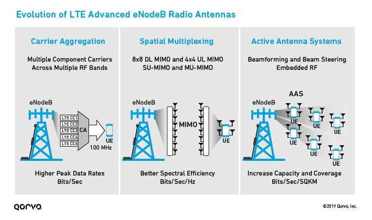
The Active Antenna Systems (AAS) is an advanced base station platform with optimized cost, structure, and performance. 4G Release 12 enhancements significantly impacted how enhanced NodeB (eNodeB) radios are designed. Release 12 items included new combinations of carrier aggregation, spatial multiplexing enhancements with downlink MIMO (multiple input/multiple output), and RF requirements needed in AAS. This first figure summarizes portions of the Release 12 items with respective features and benefits.

MIMO technology uses multiple antennas installed at both the source (transmitter) and destination (receiver), to improve capacity and efficiency. As shown in the previous figure, more antennas equals more data stream layers. This results in a bigger data pipe to a single user or multiple data pipes to separate users, also known as multi-user (MU) MIMO.
Massive MIMO takes MIMO to the next level. Today’s MIMO deployments typically consist of up to eight antennas on the base station and one or two antennas on the receiver. This allows the base station to simultaneously transmit eight streams to eight different users or double down and send two streams to four users. Massive MIMO scales to dozens or hundreds — theoretically thousands — of antennas, providing capabilities and benefits that include the following:
- Vastly improved capacity and reliability
- Higher data rates and lower latency
- Better connections (especially with the challenging higher frequencies to be used for 5G)
- Less intercell interference
- Greater efficiency and better signal coverage enabled by beamforming
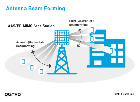
The next figure illustrates how an AAS/full-dimension (FD) MIMO base station can direct beams in both the horizontal and vertical directions. This operation dynamically points the antenna pattern on a per-user basis, providing a better link and higher capacity to that user. In turn, this allows him to offload his traffic and free the radio resources more quickly, which can then be used by others, resulting in a net increase in aggregate capacity for the entire cell.

The next figure below illustrates how AAS uses beam steering to provide end-to-end Fixed Wireless Access (FWA) connectivity to Customer Premise Equipment (CPE) located in commercial buildings and residential homes.

Go in Depth
Learn more about 5G FWA systems:
- 5 Things to Consider When Designing FWA Systems
- 5G Fixed Wireless Access Array and RF Front-End Trade-Offs (Microwave Journal, Feb. 2018)
- Delivering 5G mmWave Fixed Wireless Access (EDN, Sept. 2017)
One of the obvious advantages of 5G FWA is its ability to support very high peak data rates without requiring dedicated fixed facilities for each individual user. To enable higher peak data rates and greater system capacity, FWA radios will make use of new higher frequency bands from 24GHz up to 42GHz and potentially even higher.
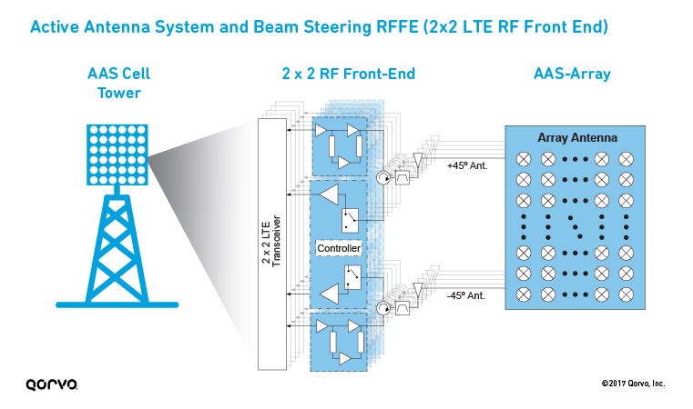
Using larger antenna arrays provides additional beamforming to overcome more severe propagation challenges encountered at mmWave frequency ranges. These arrays can have hundreds of elements but due to the short wavelength are extremely compact. For example, a 64-element antenna array at 30GHz is only 40 mm x 40 mm. Large arrays provide very focused beams that can be redirected in less than a micro-second. In addition, the large phased array can act as a single array or as multiple independent subarrays with unique beams directed to service multiple user terminals simultaneously on the same frequency resource. The following figure shows a block diagram of the 2x2 RF front-end modules in the per-antenna RF subsystem of an AAS antenna array that comprises an AAS cell tower.

Want more details about what's to come with 5G? Download a copy of our latest e-book, 5G RF For Dummies.
– Excerpted with permission from John Wiley & Sons, Inc., from 5G RF For Dummies.
Have another topic that you would like Qorvo experts to cover? Email your suggestions to the Qorvo Blog team and it could be featured in an upcoming post. Please include your contact information in the body of the email.
